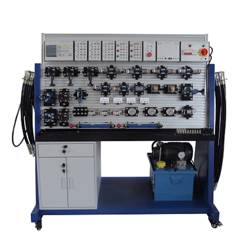
MR110M Electro-hydraulic Workbench For Training (Double Sided) Teaching Equipment Didactic Equipment
Electro-hydraulic workbench for training. Equipped with 60 bar hydraulic power unit, maximum flow 3.2 L/min
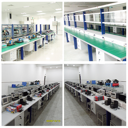
Mobile unit (rolling table) of modular training system
Equipped with slotted plate and grille to reduce rapid tool installation
(ZMH1108) PLC Electro Hydraulic Trainer
 I. Introduction
I‘s suitable for schools, engineer training centers, factory training department etc.
Through this trainer, students can master hydraulic components structure, hydraulic circuit control theory, hydraulic circuit design, and hand on ability for hydraulic trainer.
This trainer is flexible and students can design their own hydraulic circuit.
II. Technical parameter
(1) DC power: input AC 380V,50Hz Output: DC 24V/3A
(2)Wheel: 4, 2 lockable with brake, 2 not lockable
(3) Hydraulic station:
nominal volume: 35L
rated output hydraulic pressure is 16MPa,
pump type: gear pump
(4) Slot space:25mm
(5) Panel material: aluminum
(6) Workbench type: single side two work station for 2 students
(7) Hydraulic station with hydraulic oil
(8) Whole equipment dimension:1600mm(L)×750mm(W)×1700mm(H)
(9)Aluminum panel dimension: 1200(L)×750(W)
(10)Cabinet: 1
 III. Experiment that can be finished
1. Direction control circuit
(1)Hand operated direction valve direction change circuit
(2)Solenoid directional valve direction change valve
2. Pressure control circuit
(1)Single grade pressure adjust circuit
(2)Secondary pressure adjust
(3)Single grade pressure decrease circuit
(4)Secondary reduce pressure circuit
(5)Use “M” direction change valve ife circuit
( 6)Use selector valve ife circuit
(7)Use overflow valve ife circuit
(8)pilot operated check valve protect voltage
3. Speed adjust circuit
(1)Oil inlet throttling governing
(2)Back oil circuit throttling governing
(3)By pass circuit throttling governing
(4)Speed adjust valve speed synchronizing circuit
(5)Speed adjust valve parallel circuit
(6)Speed adjust series circuit
5. Use sequence valve sequent circuit
6. Use stroke switch control sequent circuit
7. Use pressure relay control sequent circuit
8. Use pilot operated check valve single direction lock close circuit
9. Use pilot operated check valve two directional close circuit
10. Use “O” type directional change valve close circuit
11. Relay control hydraulic basic circuit
12. Hydraulic component capacity measure experiment
 IV. Configuration list
No. Name Unit Qty.
1 Training workbench Unit 1
2 Aluminum base panel Unit 1
3 Pump hydraulic pump station Unit 1
4 Electrical hanging shelf pc 1
3 Double acting hydraulic cylinder pc 2
4 Throttle valve pc 2
5 return orifice check valve pc 2
6 Direct overflow valve pc 3
7 4/3 solenoid directional change valve(M) pc 1
8 4/3 solenoid directional change valve(0) pc 1
9 solenoid directional change valve(Y) pc 1
10 solenoid directional change valve(H) pc 1
11 Stroke valve pc 1
12 4/2 solenoid valve pc 2
13 4/2 hand operated direction valve pc 1
14 Speed adjust valve pc 2
15 Pilot overflow valve pc 1
16 sequence valve (pilot) pc 1
17 pilot operated check valve pc 2
18 Pressure reduce valve(pilot type) pc 1
19 Single direction valve pc 1
20 Pressure relay module pc 1
21 “T” connector pc 6
22 Five holes connector pc 4
23 GLYCERINE PRESSURE GAUGES pc 3
24 Oil tube, 600mm ea 6
25 Oil tube, 1000mm ea 10
26 Oil tube, 1500mm ea 2
27 Oil blocking module pc 1
28 DC power module pc 1
29 Hydraulic station control module pc 1
30 Relay module pc 3
31 Button switch module pc 2
32 Induction sensor pc 1
33 Capacitive sensor pc 1
34 Optical sensor pc 1
35 Micro switch(left) pc 2
36 Micro switch(right) pc 2
37 Electrical cable unit 1
38 PTFE THREAD SEAL TAPE pc 1
39 Installation tools pc 1
40 Training guidebook pc 1
41 Electrical cables pc 25
42 English Training Experiment manual pc 1
43 Siemens S7-1200 PLC pc 1