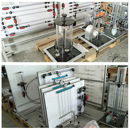
MR225E Electronics Training Workbench Variable Frequency Drive Training System Didactic Equipment
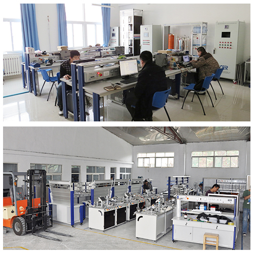
I.Overview
This equipment is to be used in technical schools, vocational schools and colleges for 228 electric experiments include diode and triode circuit, sine oscillation circuit, DC coupling amplifier and integrated operational amplifier circuit, DC power, controllable silicon and trigger circuit, digital circuit and others.
1.Student table: size 160*80*75cm, there is a drawer on each side of the table with sockets and components retaining panel in it. The middle drawer is to keep tools, multi-meter, wires, instructions, etc. On the table, a general circuit board is laid in the middle, which is size of 150*70cm. There is four lines of sockets, which can be used to connect the components and electric appliances in required circuits. 2.Components and Sockets: as a basic component in the circuit, it has component code, component, powered socket and injection mold testing hole. It is to be used with general circuit boards. Student can connect components with the socket to form a circuit. It needs no welding at all. It is very easy to change the circuit or its component parameters.
3.Tape General Electric Experiments Table (Referred to as experiment table):
a.Power Input:
There is three-phase four-wire and ground-wire input back the experiment table, and also equips power leakage protection switch (general power switch), three-phase indication lamps, voltage meter, current meter for testing the three-phase power.
b.Power Output:
Group A: three-phase four-wire output connects socket “W, V, U, N, Ground” and a three-phase four-wire socket of 380V, 3A.
Group B: adjustable AC power, AC output current 1.5A, voltage 3-24V in seven ranges and a current meter indication.
Group C: DC regular voltage adjustable power: current 1.5A, continuous adjustable voltage 1.25-24V, voltage and current meter indication.
Group D: DC regular voltage power, current 0.5A, continuous adjustable voltage 1.25-24V, voltage and current meter indication.
Group E: DC regular voltage power, current 0.5A, voltage 5A, current meter indication.
Group F: single phase AC commercial power output 3A, for connecting external instruments and equipment. c. Function signal generator (sine wave, square wave, triangular wave)
(1) Frequency Range: 5Hz-550KHz in five bands
Band I 5Hz-55Hz
Band II 50Hz-550Hz
Band III 0.5KHz-5.5KHz
Band IV 5KHz-55KHz
Band V 50KHz-550KHz
(2) Frequency graduation: read from Hz meter, basic error ≤3%
(3)Max output voltage: Sine wave: 600Ω load, 20Hz-55KHz≥4.5V, meter shows;50KHz-550KHz≥3.5V, three steps reduction 0bd, 20bd, 40bd;Square wave: 1KΩload, 3.5VP-P;Triangular wave: idle load 1VP-P.
e. Single pulse source:
Positive pulse, negative pulse, turn the pulse-switch to output the pulse.
f. Audio power frequency amplifier:
Input sensitivity≥5mV, Output power≥1W, adjustable volume, preset horn, used in audio amplifier circuit and also used as signal tracking instrument. e. Protection Circuit:
(1)General power switch (leakage breaker): connect with the three-phase four-wire input terminal for protection of three-phase and single-phase leakage ,overload as well as getting an electric shock . Current of leakage acting switch <30mA.
(2)General Fuse: three-phase input fuse UFu, VFu, WFu(3A), if users require current of 3A or above, then you should change the other fuses. (below 10A)
(3)Power Switch, fuse Fu (1A): power switch for all kinds of low-voltage DC and AC power supply, function generator and audio amplifier.
I. Explanation of terms and codes
Av voltage amplification Vcc Power voltage
Avd Differential mode voltage amplification VCEO Cut-off voltage drop of triode
EO Equivalent Electromotive force Vces Saturation voltage drop of triode
FO Oscillation frequency Vi Input voltage
Ii Input current Vo Output voltage
IO Output current VOC Output voltage of double terminals of common-mode
RL Load resistance Vod Output voltage of double terminals of differential-mode
Ro Resistance of power supply VOH Output high level
UL Load End voltage VOL Output low level
Experiment table refers to electric experiment table General circuit board refers to the patent product of four-hole connection board made by our company.
Component socket refers to the plastic case and components in it. (Such as resistance socket, potential meter socket, digital integrated socket, etc.)
Socket connection circuit includes component socket, which form many different circuits in experiments.
Input power supply: connect the power supply to the power input terminal of the experiment circuit with the wire that has socket.
II. Explanation of illustrations in the electric drive experiment
In the diagram of the electric drive experiment, components in the dotted line, switches, fuses and other components in the double dotted line are all supplied together with the experiment table. You only need to connect the three-phase four-wire power terminal on the experiment table to the circuit with the wire.